
Recently on bentleyuser.org...

© bentleyuser.org 2026
Printed from www.bentleyuser.org © TMC Publications (UK) Ltd 2010
MicroStation 101: Global Origins and V7 workmode
by Karen Fugle - 09 October 2003
![]() What are global origins?
What are global origins?
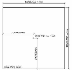
You work on what is called a Design Plane. At the bottom left of this design plane is a point called the Design Plane Origin. In the centre of the Design Plane is a point called the Global Origin.
The MicroStation J (V7) the Design Plane looks something like this picture:
(Thanks to www.askinga.com)
My design plane is 429 km x 429 km. The size of your design plane will vary according to the number of positional units set in Settings>Design File. My positional units are 1m:1000mm:10pu. To understand these units refer to the MicroStation 101 on Positional Units.
The Design Plane for V8, however, has been greatly expanded. In fact its about 2 million times larger in each axis!
Thats a very big area to draw in. But, (theres always a but) MicroStations accuracy drops off the further away from the V7 Design Plane your elements are!
By default, the Global Origin is assigned the xy value of 0,0.
To give true or world co-ordinates (Northings and Eastings), it is possible to move this point or re-assign a co-ordinate value to it.
The Global Origin can in fact be any point inside or outside the Design Plane but your drawing has to be contained within the design plane.
When we move the global origin your drawing doesnt move on the design plane but the co-ordinates do. All your co-ordinates are based around the Global origin point.
Ok, so where do the problems start?
The problems are encountered when your drawing, or one of your reference files, is outside of the design plane.
When you open (or close) a drawing you will get this notice:
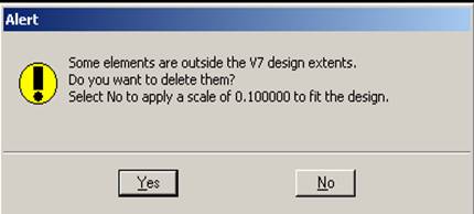
Eeek! What do I do?
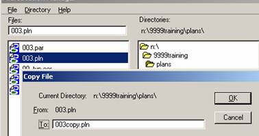
Stop where you are. Get someone else to browse for you file in MicroStation Manager and take a copy of your file.
Highlight faulty file
File>copy
Rename the new copy of the file so that you know its a copy.
Once someone has done this for you click on YES to delete the elements that are outside the design extents. This may delete some of your drawing which is why we needed the safety of a backup copy.
What do I need to do to fix this?
Firstly you need to establish the global origin point in your faulty drawing:
1. How do I locate the Global Origin 0,0 in my drawing?
Start the first point of a line. Hit the letter P on your keyboard. A Data Point Keyin box will pop up. Make sure it says Absolute(xy=) and type in 0,0 then hit enter on your keyboard.
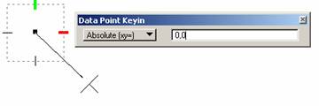
The line will be drawn to the point 0,0.
You can check this if you like by switching your tentative button to LOCATE (keyin SET TPMODE LOCATE). If you now tentative on the end of the line it will show the coordinate 0.0000,0.0000 at the bottom of your screen.
2. How can I establish the co-ordinate this Global Origin is at?
Type into your keyin box go=$ and hit enter. The Co-ordinate will be displayed at the bottom of your screen, next to the message center box.
Go = 214748.3648, 214748.3648
(NOTE: Your global origin may not be the same co-ordinate readout as mine. The position of the decimal point may vary according to your Positional Units. My Positional Units are 1m:1000mm:10pu. To understand these units refer to the MicroStation 101 on Positional Units.)
3. My Global origin is correct, now what?
Smile!
4. My Global origin is wrong.
A new drawing with the correct origin will be created. Your drawing can then be referenced into the new drawing and copied through live, with a nest depth of 1.
Or step 5 or 7 will be applied.
5. Correcting the Global Origin point with a keyin
A keyin can be used to correct the design plane either on its own or as a batch process.
go=0,0;xy=0,0|uor (the pipe | is achieved by using the Shift key plus \.)
This keyin will shift the global origin point to the design plane origin then relocate it again to the centre of the Design Plane.
6. Can I see the extents of the Design Plane area for V7?
You can create a cell to make it easier to see the Design Plane area. (You will need both MicroStation J and V8 versions to do this.)
Open a V7 dgn in MicroStation J that you know has the Global Origin in the centre of the design plane.
Type in go=$ and hit enter and write down the co-ordinate displayed at the bottom of your screen.
Draw a line from your Global Origin (refer step 1), using the written down coordinates, to the Design Plane Origin.
e.g. My co-ordinate for the Global origin is 214748.3648,214748.3648. So I can draw a line from 0,0 to -214748.3648,-214748.3648. (Your decimal point may vary.)
Now that you have located the Design Plane Origin you can draw a square the size of the Design Plane, from this point. (My square is 429496.7296m².)
Open your V7 design file in V8 to draw this square. Because the design Plane is bigger in V8 you can zoom out to see it.
Offset it by 500m inside. Make it into a cell with the insertion point being your global origin).
Open the design file again in MicroStation J and to check. You shouldnt be able to draw beyond 500m outside of the cell V7 simply wont let you.
As a check the cell can be inserted into drawings.
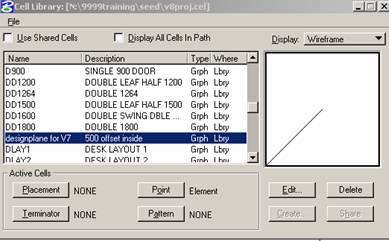
The cell is a square with a line from the bottom left hand corner to the centre point.
As you insert the cell highlight the Accudraw dialog box and hit P on the keyboard. Make sure it says Absolute(xy=) and type in xy=0,0|uor then hit enter on your keyboard. This will make sure the cell is inserted at the centre of the design plane every time.
The square is 500m smaller on every side than the V7 design plane area. You drawing should ideally be near the centre.
Take care if your drawing is near the edge of the design plane. If it is too close you may need to discuss moving it with your CAD Department.
Also check the position of the reference files. If any of these are outside the design plane they will also cause problems for your drawing.
7. Can I use the cell to relocate my incorrect origin point to the correct place?
Yes, reference the cell into your dgn. If you locate the origin point (as in Step 6) you will notice that it has the wrong co-ordinate and therefore not in the correct place.
Keyin go=0,0 and then press enter. You will then be prompted Global origin > Enter monument point. Tentative on the end of the line in your cell. Check again (using step 1) to check that the center of the Design Plane cell is now in fact your origin point 0,0.
8. Is there anything else I can do to prevent problems occurring?
Check your seed files all have the same origin point and unit settings.
Always start drawing your grid at the point 0,0. Do not move the grid and use it as a reference file and starting point for all other drawings.
Try to create drawings from a correct seedfile rather than using Save As.
Always attach your reference files coincident.
When a file is referenced in, its design plane is matched to the design plane of the active file.
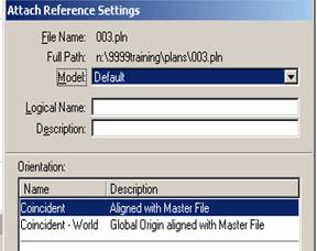
(In other words, using Coincident matches the Design Planes together and using Coincident-World matches the origin points together.)
Always talk to your CAD Department about moving the global origin point for use with OS co-ordinates or maps. Remember that changing the global origin does not move the location of the drawing in the design plane, it merely changes the co-ordinate readings.