
Recently on bentleyuser.org...

© bentleyuser.org 2026
Printed from www.bentleyuser.org © TMC Publications (UK) Ltd 2010
The not quite 100 page guide to the AEC (UK) Level Standard
by Karen Fugle - 10 September 2004
![]() Do you need to implement a new level standard? Is the old V7 level standard frustrating your users when you know that you can have infinitely more levels in V8? Like you, I've heard about the new AEC (UK) Level Standard. Sure, I thought, sounds like a good plan, but will this scare my users into never using levels again? I figured I'd better get some advice on this standard to see whether it was a good move. I went to one of the creators and resident writer for Bentleyuser, Nigel Davies, a self-professed expert on anything and everything. I knew that ND could give me the rundown without running for cover under the onslaught of all my questions. Here's what I discovered;
Do you need to implement a new level standard? Is the old V7 level standard frustrating your users when you know that you can have infinitely more levels in V8? Like you, I've heard about the new AEC (UK) Level Standard. Sure, I thought, sounds like a good plan, but will this scare my users into never using levels again? I figured I'd better get some advice on this standard to see whether it was a good move. I went to one of the creators and resident writer for Bentleyuser, Nigel Davies, a self-professed expert on anything and everything. I knew that ND could give me the rundown without running for cover under the onslaught of all my questions. Here's what I discovered;
The people background
A whole lot of people that nobody seems to know went and invented the BS1192 part 5, a UK standard for exchange and format of digital data. It's a framework, not a solution and not definitive at all. Part is mandatory and part is optional, but people tend to treat it like it's all optional.
Then the AutoDesk user group came along and declared that it was silly. They created another one for AutoCAD commonly known as the "whitebook". This was adopted more widely but it was still deemed confusing. Then this gang of MicroStation blokes got together at a Bentley Community conference and said "this doesn't work any more, it's out of date, we don't all want to reinvent the wheel". They set out to create a national layering standard; not just something that worked for their companies. More and more people thought it was a good idea and ta da, here it is today, sitting ominously on my desk!
The techie background
Well, certainly the file naming part of BS1192- 5 could be said to have be based around Arups standard at the time of creation. In fact I can quote "it's pretty much a straight lift from Arups naming standard". Arup, don't sue me; sue the guru! Anyway, it wasn't quite what everyone else wanted to do. Two of the AEC creators were from companies heavily reliant on specifications and so developed the need for a more definitive standard.
Thanks guys!
The AEC (UK) Standard is based on the BS1192 part 5 but it uses it in conjunction with the Uniclass classification system - the difference ND espouses is like buying an Ikea flat pack instead of a tree and saw.
Ok, I said, so where do I start? And he said "throw it in the bin". I thought he was kidding but I did it anyway - "standards, pah, who needs them" I said as it missed and flew all over the floor. "Look at your needs", said the guru. So here I am, thinking about whether we need certain levels out of need or convenience.
Do we really need to differentiate between drylining plasterboard walls and demountable walls? In a plan, do we need to differentiate between an internal and external wall, whereas in a section do we want them separated into general walls, interior walls and exterior walls?
And then the mighty one suggested I might like to think about the stages a project goes through. "Blimey - here we go", I thought, "I'd better find a pen!" Lets see what this code is about first!
How does it work?
There are five fields, the first three are mandatory, and the other two are optional.
1: Agent - Discipline
Choose one or several for your company.
A = Architect
I = Interior Designers
C=Civil Engineers
Etc
Example A
Architect
2: Element codes
Choose one or several fields you wish to use.
F = spaces
G = elements for buildings
H = elements for civil engineering works
Z = non classifiable layers
Example A-G
Architect-Elements for Buildings
Use the Element codes to specify your elements:
Example A-G25
Architect-Elements for Buildings (Walls)
At this point you can take the cad standard apart and put away the tables you don't need!
3. Presentation
Mostly I've seen the use of all except Constructions.
C = constructions
D = Dimensions
G = Graphical elements
H = Hatching, shading/fill, pattern
T = Text
Example A-G25-G
Architect-Elements for Buildings-Presentation
4. User Defined Abbreviated Description
Try and restrict your Abbrev. Desc.'s to a decent size. They have provided you with common examples in the code but remember you can change these or add your own. Just make sure you are clear.
Mezz = Mezzanine
Para = Parapet
Wndw = Window
Etc
Example A-G25-G-WALL
Architect-Elements for Buildings-Presentation-Description
5. View
Remember these are optional, don't need then don't use!
Fwd = forward of section cut line
Hid= hidden from view
Rfl = reflected above section line
Sec = on section cut line
Example A-G25-G-WALL-SEC
Architect-Elements for Buildings-Presentation-Description-View
Where are you at?
I decide I'm going to work with A for Architect and the Building components F, G and Z and all the presentation codes except C. The other parts I choose to opt out of in order to simplify my code. The rest of the cad standard I put out of sight! My resulting example looks like this:
Example A-G25-G-WALL
Hey, and you know what? The descriptions are a guideline!! Woohoo I thought lets get carried away and change A-G25-G-wall to A-G25-G-NiceHighClassWall. Second thoughts, best to keep it short and sweet!
How do you put it all together?
Ok, now I know that sometimes we in the CAD industry like to think of ourselves as top technological nouses, but when the all-seeing-one announced that I should "always work to the lowest common denominator", I thought riiighhhtttt...here we go, I've spent most of my life in appreciation of my Irish ancestry and my red hair, was I now going to need a blonde makeover to get the best of the system here? Well, the Norwegians may have a head start (head start - get it? Oh, never mind) but I assure ND that I can revert to type with a blonde wig in hand.
So the downfall is that the standard is extremely flexible (but not as much as a tree and saw) and that people don't know how to appreciate how it can be used. The AEC Standard doesn't give guidelines precisely so that people figure out how to use it for themselves. Hmmm I think, this is nice logic but it's more likely that people will just use it incorrectly or not use it to their full advantage. Right, I think, it actually needs a touch of redhead!
So, I've built a minimum level, lets have a look at some variations on the theme!
Remember this level is where I am going to place my wall elements.
Example A-G25-G-Wall
How do you want your text?
If you wish your text associated with an element my code could look like this:
Example A-G25-T-Wall
If you wish to place all your text on a separate level then your code could look like this:
Example A-Z000-T-Annot
Is your code advanced enough?
It could just be a simple additional number from the AEC Standard that defines your wall type;
Example A-G25-T-Wall
A-G251-G-WallExtl
A-G252-G-WallIntl
I know that your thinking you're so impressed by this but hey, lets throw caution to the wind and really get down to the serious stuff!
The advanced codes are taken from the Uniclass J tables "Work sections for buildings" (based on the National Building Specification).
The Guru says:
"The advanced version codes, intended for use by specialised design professionals, working of the most complicated of design projects, or those having specific requirements for the division of their layers..."
Does that sound like you? Not if you're thinking with that blonde wig its not! But, maybe you need to ask yourself how well defined your users wish the code to be.
By adding the codes from the J Tables you will define your wall more precisely. For instance JK10 = Plasterboard lining.
Example A-G25:JK10-G-WallPlbd
Aren't there always 10 ways to skin a cat?
You got it. Before I defined my external wall like this
Example A-G251-G-WallExtl
But using the J tables I could do it like this:
A-G251:JF1-G-WallExtl
Hmmm....think I know which one the blonde would prefer!
And there is also the issue of how the building components are defined:
The code for a window is G321 and the code for an external wall is G251 combining them would mean I get:
A-G321:G251-G-WndwExt
The G321 only defines a window and not any further, you need to take the internal or external wall code to define its use absolute!
And, yes, you could always define the wall first:
A-G251:G321-G-WndwExt
And so for Internal windows:
A-G321:G252-G-WndwInt or A-G252:G321-G-WndwInt
And roof lights:
A-G321:G24-G-WndwRoof or A-G24:321-G-WndwRoof
Oh cripes I think, lets put the blonde wig back on so we can think about that lowest common denominator again!
By this stage I have defined a minimum level list but because I've kept the codes short I've neglected to define the actual materials e.g. concrete, glass, plasterboard etc. Perhaps I needed those J tables after all! I don't want to double up codes so I opt to replace the G codes with the J codes. This way all my materials will be defined but generic in their lack of association to a particular building element.
Example of what I do not want A-G25:JK10-G-WallPlbd
Example of what I want A-JK10-G-Plbd
Keep it pure I say! 100% pure! Like New Zealand! ...Sorry, couldn't help it.
Ok, I'm getting the hang of this now...but...
Why the need for an abbreviated description when we have the full description column in Level Manager?
Well, says the guru, for a start AutoCAD doesn't have a Description column in their Level Manager so we had to put an abbreviated description in the AEC code to keep them happy!
As an aside, because maybe you need an aside by now, not that it's that interesting but I'll tell you anyway.... AutoCAD can't handle the ":" in the code and converts it to an underscore during a MicroStation conversion. Ok, not that interesting...moving on!
There's no stopping the old reverent one now - he's on a roll, just when I think I may have this code slightly cracked he goes and throws another spanner in the mix:
How does it relate to your process?
So I thought about the concept stages and whether we needed to define the spaces. Is there a reason for us to tell clients how much office space vs utility space there is? If the answer is yes, then maybe I'd like to analyse the information independently from the rest of the space. Hmm...time to organise a meeting and get some user feedback!
Concept Stage Table F is about spaces.
A-F3-G-Circ is a circulation space.
Scheme Stage Table G is Elements for Buildings
By this stage you have your floor plate defined and you know where your walls are. Table F isn't definitive enough so you will need to use Table G.
A-G25-G-Wall
A-G22-G-Flor
And hey, want to define different types of wall but don't know what they are?
How about a little poetic license?
A-G25-G-Wall1
A-G25-G-Wall2
A-G25-G-Wall3
Extreme Ironing (www.extremeironing.com for those of you who ask) is so last year - I want extreme level naming (well, I'm sure if those guys can iron at the top of mountains then I could think of new unchartered levels on the top of Mount Kilimanjaro!)
Detail Design
This is where the exchange of data starts happening. Where we define what materials are and how they work.
A-G251-G-Intwall
A-G252-G-Extwall
A-G25:JE4-G-WallSituConc
Hey, lets use that poetic license again and kill off that A-G25:JE4--G-WallSituConc. How about instead:
A-G252-G-ExtwallConc
Or even better:
A-G25-G-WallConc
Remember those descriptions are a guideline only!
But here are a couple of points to remember when choosing them:
1. The longer the name the less likely your users will appreciate it and the less likely you'll be able to view it all in the Attribute Level Display and other dialog boxes!
2. The better the description the easier to use the level names whilst waiting for Bentley to change the Attribute Level Display to contain not the level Name but the full level Description instead.
3. Working with people in Spain? Outsourcing to Timbuktu? Who says the full level description has to be in English? We English speaking can tell the levels is Walls from the abbreviated description in the Level Name. The Germans however can work on this level easily by changing the Full Description to be in German. Nice!
Speaking of Full Descriptions in Level Manager...
When the users see these funny numbers in front of the layer name they freak out! Never mind me telling them that it's a good way to learn the specification codes, they just want to see the full description and nothing else!
I have a plan so cunning you could put a tail on it and call it a weasel I think (in an admittedly plagiaristically Black Adder moment). All I need to do in my dgnlib is swap the level names and the full descriptions over! Then, when the Attribute Pull down displays the descriptions there'd be smiles all round! "Not so fast" said the smirking guru! Bugger. The reason why we even have a description part of the AEC standard and Level Manager is because of that species AutoCAD! Oh, god, I thought, are we pandering to them? Clipping me round the head the almighty one reminded me that the standard has a neutral platform and that its meant for AutoCAD users as well. And, getting back to the point, the reason why the AEC codes need to be in the Names column of Level Manager is to do with converting to DWG. You see, upon converting MicroStation takes the Level Name and maps it to the Layer name in AutoCAD, thus keeping your levels to a UK standard when they go out the door. AutoCAD doesn't have a Full Description Column so they would never see the AEC codes if you swapped them round and would only result in non-standard names in the converted AutoCAD file. Well, that's shown me up, I thought, better get the blonde wig off and ask something reasonable!
How does the AEC code relate to the AIA - The American version?
Example AIA (short format) A - Wall
AEC (short format) A-G25-Wall
There can't be a direct translation because of language differences. You know what those Americans are like - calling the road a pavement and calling the pavement a sidewalk, I mean how un-British can you get? (Besides, it's a footpath I tell you!)
What if you have an American office and want to implement a universal standard? You could look at choosing to combine the AEC standard with the AIA abbreviated descriptions (perhaps just agreeing to differ on the terminology of descriptions like pavement!).
How do you manage the migration of old levels to new AEC levels?
Convert old level names to new level names? I can feel the headache coming on already! In fact, there's a bug there:
When using a CSV to remap you levels MicroStation has problems when mapping 2 (or more) old levels to one new one. The Level description is taken from the old level table and not the csv. It also turns levels on or off depending on the first level it comes across in the csv.
(Hint to Bentley: MicroStation should check whether a level is used before using it to remap a level. If it is unused, it should be deleted - MS_V7TOV8_DELETE_UNUSED_LEVELS = 1 or Required = 0.)
Best thing here is to start the new levels on new projects!
Don't forget you have to convert your cell libraries as well. This may mean maintaining two sets of cell libraries until all projects are on the new levels. If you are not planning on locking down dgnlibs then you may choose to let the new cells infiltrate existing projects and run with maintaining one set of cell libraries.
How do you manage the migration of levels between drawing phases?
Do you have dgnlibs for each phase or one that contains enough levels to cover all projects? Is the work likely to be redrawn between phases? I opt to try and cover all phases in the one dgnlib. Is anyone likely to remember to change the dgnlib between phases?
How do you make it easy for the users to find the right level quickly?
Filters - use the hierarchies to filter the information:
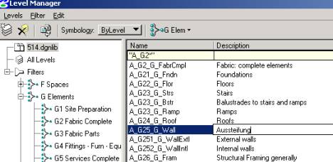
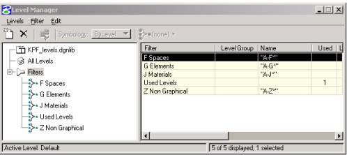
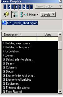
You can see I have filtered my levels by their Element Code. This is done simply by specifying the first part of the code in the Name column eg "A-F*". I have also created a filter just for Used levels by placing a 1 in the Used Column.
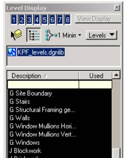
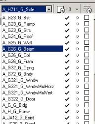
I also made it easy for my users by putting the Element code before the full Description - this will make them filter in alphabetical order by code (eg F series) inside Level Display. Much easier to select the correct level! (Yo, Bentley, wouldn't it be good if you could drag and drop your levels into a filter!)
Don't forget how you named your levels if you used double codes;
Do you want Internal windows filtered under "A-G32*" you will need that code to appear first in the level name, otherwise it will filter under the Wall levels of "A-G25*"!
Example A-G321:G252-G-WndwIntl or A-G252:G321-G-WndwIntl
Or else you could create more filters I suppose, but as we keep saying, work to the lowest common denominator!
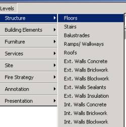
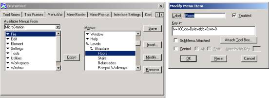
Level Pull downs are another option. Linking the pull down to the correct level number and symbology can help users select levels easily. Overkill? It could be debated!
How do you deliver the standard?
My obvious reaction here is to say dgnlib, hand the levels over and forget about them. Arh, but if only real life was this easy! I'm opting to give users what I call a minimal dgnlib - just enough for them to work on without wanting more. I do know of other companies that are or will be using a third party application that creates the levels to the AEC code on the fly - a good way to go if
A: You want users to create their own AEC levels on the fly without the use of dgnlibs to upkeep.
B. You want to give them minimum levels but let users create extra's to their file without editing the dgnlib.
As for locking down your standards - well, we're back to looking at processes again. If you use _USTN_CAPABILITY to stop the creation of new levels, you need to be aware that anytime you want to copy an element from another file, with different level names, the element will drop onto the Default level with the default symbology. Bummer. Still using that old archiving stalwart FF= to merge drawings for archive or issue? These non - standard levels won't merge properly and may appear on your resulting File Fenced Dgn on the default level again or not at all! Another bummer.
And if you don't lock your levels then non-standard levels are going to leak into your file left right and centre. There is no way to cure this except rely on the user to shift the elements to the correct level.
Taking that blonde wig off I remember that we have actually asked Bentley for the ability to lock users from creating levels in a dgnlib, but for all other functions (e.g. FF= or Batch Merge) it be ignored.
Nearly all questioned out..I've got time for one more!
Architectural users don't like codes! How do I convince them?
Yeah, so it's easy for those engineers to grasp! They like codes! They like standards! They like structure! We architects need freedom of expression, and that means in MicroStation too!
"Oh shut up" said the Engineer Guru, and then he threw a nice quote my way. But it was so good I went to the site to quote them all.
Courtesy of the National CAD Standard this is why we standardise:
* Consistent classification of data for all projects, regardless of the project type or client.
* Seamless transfer of information between architects, engineers, and other design team members.
* Reduced preparation time for translation of electronic data files between different proprietary software file formats; predictable file translation results.
* Reduced data file formatting and set-up time as a result of adoption of the Standard by software application vendors.
* Greatly reduced staff training time to teach "office standards."
* Streamlined drawing checking process for references, omissions, etc.
* Automated updating of data files as the Standard evolves.
* New opportunities for expanded services and revenue beyond building design.
* New marketing opportunity; design firms complying with the Standard can feature that compliance as a benefit to prospective clients.
I really couldn't have said it better myself!